26.09.2017 ~ 20.10.2017
– Control Overview
- What other ways can we use to control a computer, other than simply using a keyboard and a mouse? This project seeks to explore a range of hardware input methods – buttons, switches, sliders, knobs – and how, when used singly and in combination, they can affect computer-based realtime environments. We will explore the technicalities of how to build simple control circuits using Arduino and Firmata – creating a ‘control bank’ – and develop further our understanding of how to make responsive digital artworks. You will also be introduced to soldering and laser cutting techniques.
- The project is based around the keyword control. Consider this word both in its literal and in its wider contexts – the notion of controlling; forced control; expressive control; control as having both positive and negative connotations.
Week 1
“Control” project is a research of “What other methods can be used to control the computer besides simply using a keyboard and mouse?” Explore a variety of hardware input methods, including buttons, switches, sliders, and knobs. It is a project that creates things that can affect a computer monitor-based real-time environment, either alone or in combination.
The aim of this project is to explore techniques for creating simple control circuits using ‘Arduino’ and ‘Firmata’, and to gain a better understanding of how to create responsive digital works. It also introduces soldering and laser cutting techniques.
The project is driven by the keyword ‘control’. The word is literally meaning or in a broader context-the concept of control: forced control, control of expression. Control is considered to have both positive and negative meanings.
This project uses ‘Arduino’ and ‘Processing’. To introduce these two briefly,
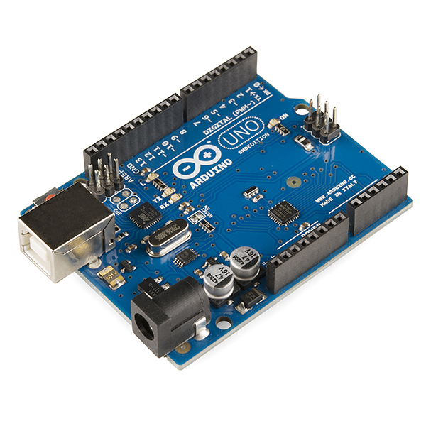
-‘Arduino’ is a board that can connect various sensors or components and includes input / output and central processing unit. It can also take input from various switches or sensors and control the output with electronics such as LEDs and motors to create objects that can interact with the environment.
For example, a variety of developments are possible using Arduino, ranging from simple robots, motion detectors, sound devices, Internet of Things (IOT) and media art. In addition, Arduino’s circuits are open-sourced, so anyone can create and modify their own boards.
‘Processing’ is a program that allows artists to easily produce visual feedback. It also includes the purpose of teaching visual programming languages using visual effects. So ‘Processing’ is based on ‘Java’ but uses a simplified syntax and interface. Processing is mainly used by artists working in digital art and visual design.
We use these two programs to create a work where the audience and the screen can interact. Two tutors joined us for this project.
9.26
On 26 September, I got a rough overview of the project and the upcoming class schedule from tutors.
9.28
On 28 September, I heard a description of the project. Tutors explained first about the submission form. We have to use switches, sliders, knobs and buttons. In response to these four input devices, I need to produce the result of computer and human interaction.
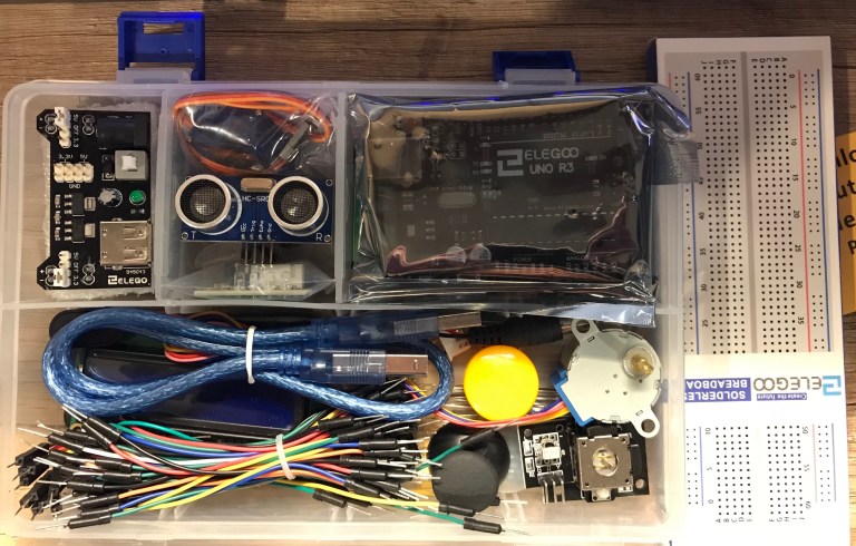
After explaining the description of the project, tutors gave a start kit of Arduino and information about Arduino. Course was started with “What is Arduino?”, When was Arduino created and for what purpose? And tutors explained the areas used.
The theoretical part has been explained, and the actual steps have been taken. Tutors took out ‘Arduino Uno’ and explained the role of each part. ‘Arduino Uno’ consisted of analog and digital pins, timer sensor, CPU and so on.

Tutors also explained about the included ‘Breadboard’ like ‘Arduino Uno’. ‘Breadboard’ is a solderless board that can be used and reused to prototype electronic circuits. We can try different wire circuit layouts and sensors connections before soldering.
Tutors also gave some explanations of the electrical characteristics, components and the Arduino program.
First, a discussion of ‘High Impedance’, ‘Pull-up’, ‘Pull-down’, how ‘Digital’ and ‘Analog’ are different, and the types of sensors and resistors included in the Arduino kit.
High Impedance – When the digital pin is set as an input, the voltage goes back and forth between LOW and HIGH. This is called floating state. To prevent this, the voltage must be fixed, which can be prevented by adding a resistor.
PULL-UP – A circuit that implements a resistor towards 5V is called a pull-up resistor.
Pull-down resistor – A circuit that puts a resistor on the GND side is called a pull-down resistor.
Digital is a opposite meaning to analog, refers to the amount that the value is an integer multiple of the minimum value at any time and does not take any other intermediate value. As a specific example, there is a digital clock. Digital clocks have no ambiguity and can increase precision because they handle data one by one.
In addition, it means not continuation but divided independently. It can also be displayed as 0 or 1, like a switch button. In Arduino, it is recognized as 5V and 0V. In Arduino, we can read the value with ‘digitalRead’. If electricity is present, it is either HIGH (1) or LOW (0).
Analog refers to physical quantities that continuously change, such as voltage or current. It’s a contrary to the intermittent, digital counting.
Contrary to digital, it is connected continuously. To control an analog pin in Arduino, set the analog pin’s voltage to a value of 0~5V. The ‘~’ mark on the digital pin side indicates that an analog output is also possible.
Inputs are from A0 to A5. 0V is 0 and 5V is 255. 256 levels of expression are available. Analog also has a floating state, so, voltage lockout is required. In Arduino, you can read values from 0 to 1023 with ‘analogRead’. 0V is 0 and 5V is 1023.
After that, tutors explained the interface of Arduino program. After the explanation, we took out the Arduino Uno board and made sure the board was working properly. In the program window, compile and upload is located on the upper left, and serial monitor on the right. And in the setting, it was necessary to set the port connected and Arduino board type.
After explaining the interface and connecting one LED, I loaded the LED Blink from the basic example and uploaded it to the board. We also constructed a circuit that turns on the LED by pressing the button and turns it off when not pressed. We also made a knob to adjust the brightness of the LEDs.


9.29
On 29 September, I had a lecture linking Arduino to Processing. We had to find a code example called ‘Firmata standard’ from the Arduino programme, then upload it on the Arduino board. And download and add the Arduino library on the Processing. Through that process, Processing can recognize the Arduino board by loading the library.
After explaining how to connect between programme and the board, tutors showed us an example of the Processing code that change the size of the circle and the location of the rectangle with the buttons and knobs. However, we needed a lot of effort to approach to make them work.
Week 2
The project is on its second week. I had to make a prototype.
10.2
On 2nd October, there was a lecture about what is a prototype. A prototype is an early sample, model, or release of a product built to test a concept or process. It is a term used in a variety of contexts, including semantics, design, electronics, and software programming. A prototype is generally used to evaluate a new design to enhance precision by system analysts and users. Prototyping serves to provide specifications for a real, working system rather than a theoretical one. In some design workflow models, creating a prototype (a process sometimes called materialization) is the step between the formalization and the evaluation of an idea. However, this lecture taught me how to prototype in what form.
To summarize what I have learned in the lecture, the main points of the prototype are Appearance / Behavior / texture / Weight / Layout / Interaction / Color / Geometry / System level / Manufacture. And methods include Sketch / 3D modeling / Animation / Video / Schematics / Story boarding / 3D printer.
Then, tutor recommended a book to read that helpful to develop our ideas and prototyping. The title is “Interaction Design” and published by “WILEY”.


10.3
On 3rd October, there was a lecture about how to do soldering. I need to book a time on the canvas(portal), and tutor introduced what should I careful on soldering and how to do it.
The soldering method is as follows.
– Before soldering, open the studio door to ventilate and turn on the mini fan.
– When the soldering iron is sufficiently heated, wipe the head of the soldering iron with a sponge(?).
– Hold the soldering iron and dissolve the lead on the PCB board. The successful soldering shape looks like a towering mountain. If it is wrong, use to tool of dissolve and remove the lead.
Cautions
– Use safety goggles and must be to do ventilation before and after use.
– When not in use, do not hold it in your hand please put it on a cradle.
– Do not hold the lead too close, roll the lead when hold it away. Because It can burn your hand.
– Do not breathe in lead when it is dissolved.
– After finishing soldering, you must be clean your hands using water without touching any other place.


10.4
On 4 October, there was no lecture and just time to work alone. I looked at the submotors and the various functions of Arduino. However, nothing was used until the end of this project.
10.5
On 5 October, seeing some sample work brought by tutors and then I presented ideas about what I will do for this project in the AV room from 1:00 to 4:00 to tutors and friends.
I was trying to create an oriental painting tool using a motion tracking sensor. But as I listened to other friends talking, I realized that I had misunderstood the project. This project is not for using motion tracking sensor and etc. it just only can use four sensors that I mentioned on the above. So, I changed my ideas within a second, and I said that I had a plan to make a game or a stage setup using buttons and knobs.
Above idea was just an improvisation, so, I should have thought seriously about what to do during this project after the presentation. As I pondered what to do all afternoon, I thought it was okay to make an animation that I wanted to make before. It was a great opportunity for me to exploration and make animations that interact with the city.
The only problem left was to think about how my work communicates with the audience and what the word ‘control’ means in my work.


10.6
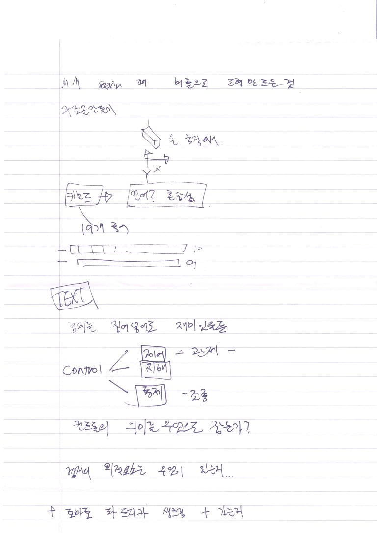
On 6 October, I started make an idea notes to make an animation. The choices given me were ‘buttons, sliders, knobs and switches’. It was a big problem to how many sensors I will used. Using a lot of buttons will allow viewers to put in a variety of features, but I’ll have trouble writing code. So, even though I used a few fewer buttons, I thought more about what would be simple and unique.
And I found identity that makes me different from others is the drawing. So, I planned to draw all the animated backgrounds and humans by hand. I plan to use two methods, one for Photoshop and a tablet, and the other for scanning with a pencil on paper. In the former case, it meant a challenge to the new method, but it had a disadvantage that it was time-consuming.
In addition, I thought about other functions that when viewer pressing a button that will triggers fill the building or background colour randomly, changing the weather, and so on. And I thought about where the background location would be. I also thought about screen resolution, and I thought 7680 * 1080 would be enough. In addition, when I reached the end of the screen, I wanted to add an effect that would reverse the character and change the background.
In the ‘control box’ design, I plan to design like the gamepad. The buttons are arranged so that the left and right buttons move in the x position, and the up and down buttons move in the y position. The only thing that can be manipulated by this button is the ‘I’ inside the animation. And why I chose ‘I’ as a controllable object was a matter of think further. In addition to the four buttons, I was going to put two knobs, and I wanted to have the effect of changing the weather or changing the season or night depending on the input.
Apart from the buttons, I tried to change the motion of ‘I’ inside the animation according to the weather. For example, when it rains, I open my umbrella and so on. And I have planned the most important time. The time allocated for drawing and writing code was three days each. And in the last week, I was planning to complete a film, sketchbook or blog.
There were a few problems in planning so far, the first problem was “how do I run a GIF file in Processing?”. The second problem was “whether the background can be followed by the character’s movement and there was not will be problem with if the resolution is increased only horizontally?”. And “is it possible to show perspective inside the screen?” Was the third problem. The questions I will ask to the tutor.
Finally, I assumed when this work was completed and thought about what interactive experience the animation would give the audience. Is it visual, auditory, or complexity? And what is the aesthetic and theoretical meaning in my work?
Below images are idea note I did.


Thank you for reading my blog 🙂
The Glasgow school of Art
Interaction Design Year 2
YongWon Choi
