
Week 3
10.9
– On 9 October, I developed idea continuously.


10.10
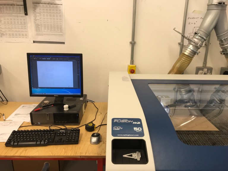
– On 10 October, there was a laser cutting introduction. In this ‘Control project’, I had to make a box for cover the board after soldering. In the case of laser cutting, it was a very convenient tool that saved the scope and time of work, because it was possible to cut the all shapes drawn by Illustrator and to use various materials.
It was even more exciting to see laser cutting in the afternoon. In this workshop, he explained how to use the machine, what kinds of materials we can use, and how to make drawings. He also explained how to make a reservation the next time you use it privately.
In the case of drawings, it should be drawn as an Adobe Illustrator. Laser cutting lines are drawn in blue, grooved at normal depth, green, and red at shallow grooving. All three colors have a line thickness of 0.001 mm, and all RGB values must be set correctly (255, 0, 0/ 0, 255, 0 / 0, 0, 255) for the machine to recognize and cut.
Today was just explanation about the machine and way to use. We were going to do a box cutting for the project as a group this Friday, but it was delayed next Monday for several reasons.
10.11
There was a personal tutorial on Wednesday October 11. This was my first personal tutorial on this project. I talked about the animation plan I had in my own design. The tutors told me it wasn’t a bad idea, and tutors talked about how to materialize and realize the idea.
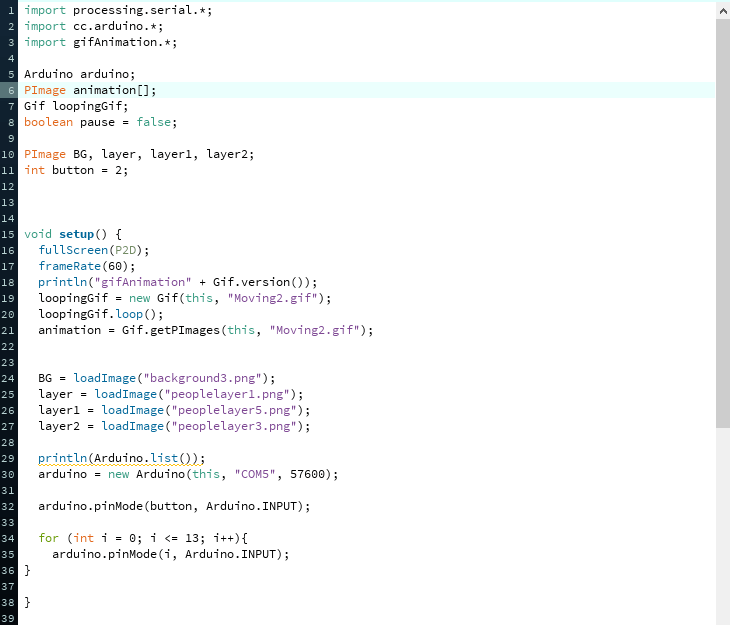
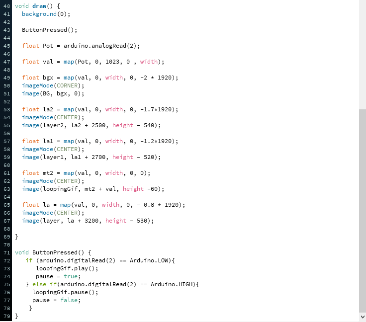
In addition, when I asked if the distance can be given by using the program, the tutors explained how to use the Processing program to give the distance by using the map function and X position matching. When the image was made of multiple layers and the screen moved to the right, if each layer moved to a different X value, an optical illusion would occur and seem to move with distance.
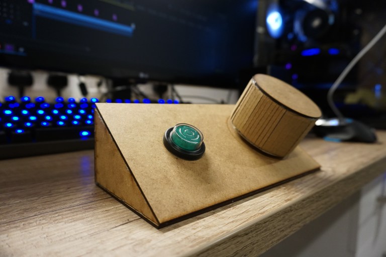
And while I was talking about box design, tutors told me that the layout of the buttons and knobs is similar to the Playstation joystick, so let’s think about a different shape and talk about the game ‘Tempast’. Rather than having a lot of buttons, it was better to simplify the operation, such as ‘Tempast’ with two buttons on the left and a rotary encoder (the potentiometer has a minimum and maximum moving value, but the rotary encoder has no limit).
Other tutor had similar opinions on this. Tutor’s suggested idea was that it would be nice to make a single knob that rotates using a rotary encoder. If I could control my work with one big slider, that can given feel like turn over the pages.
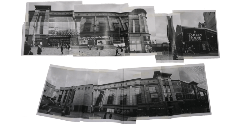
At the end of the tutorial, the work was outlined. And went into work. First, I was contemplating which places in Glasgow would be suitable as backgrounds and decided that it would be nice to have Buchanan Street in the background.


10.12
– On 12 October, I printed Buchanan Street that I took yesterday. Before the drawing, photographs were combined on paper tape to confirm the layout of the building. In the process, I can find something interesting. The places I took pictures were different, so the appearance of the building was different depending on where I took it. So, it looked a little more distorted than it actually looked. And it seemed more interesting, so I decided to draw the distorted scenery as I draw.
While attaching the photos, I concerned whether I would work with my hand or tablet.
10.13
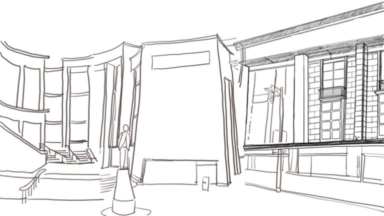
– On 13 October, I tried the Wacom tablet in the studio. The tablet was very good, similar to hand drawing. However, despite drawing about 3-4 hours, only the overall outline was drawn as shown in the attached picture below. Because of this, it may not be possible to finish the background before the deadline, I changed the plan to hand drawing.
During the weekend, I planned to finish the background and people drawing. In addition, the size and shape of the box had to be determined by next Monday. So, I made a simple prototype using paper.

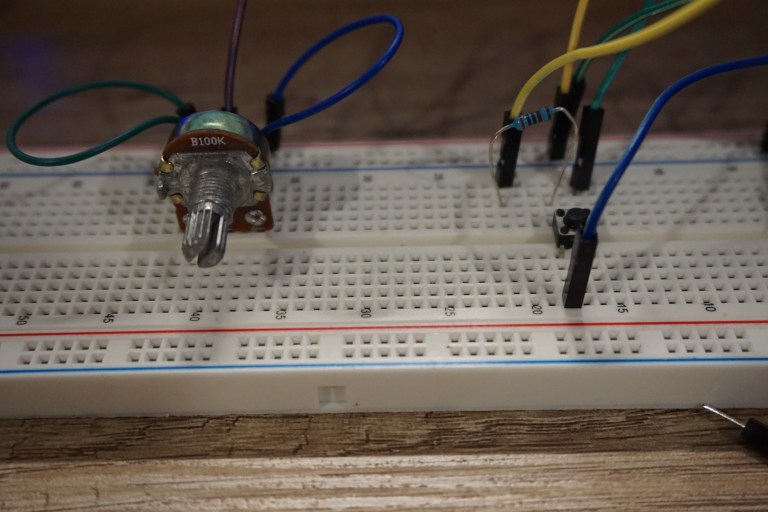
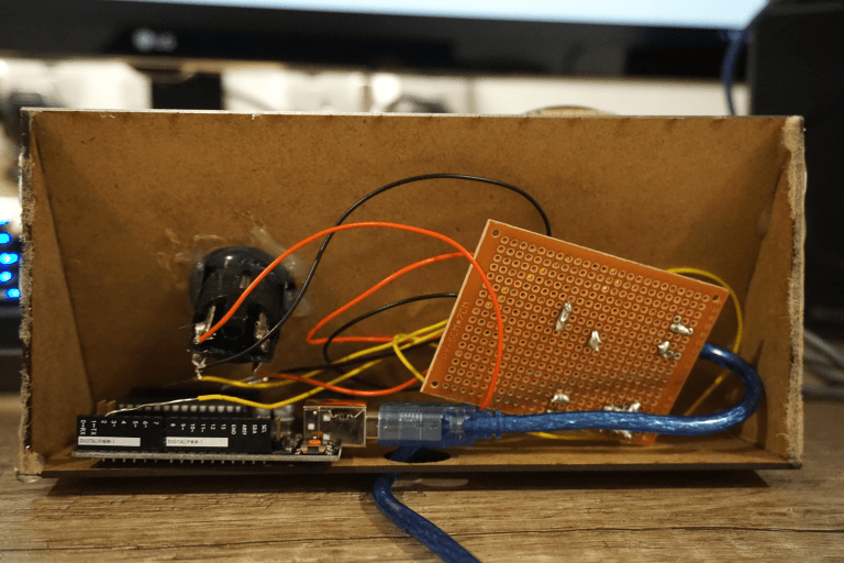
Also, the photo below is a schematic that I made before practically soldering it to the PCB board next week. It worked without a problem, so I think I can solder it.
I also created backgrounds and layers in prototype format. I tested to make sure it works in Arduino. And I should have put a GIF image in the middle of the background. My friend helped me to find a library in Processing that allows I can used GIF images.


Week 4
10.16
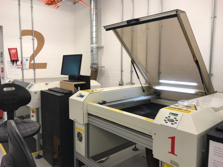
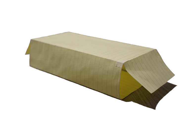
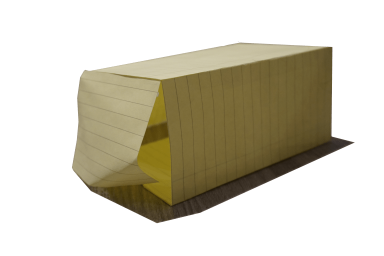
– On 16 October, ended the morning session, we followed by laser cutting in the afternoon. In the session, I made a very simple box, but other friends downloaded layout from the Internet and printed a more nice-looking box. But my box was faithful to functionality.
The reason I designed this shape box was because viewer could turn the knobs(potentiometer) a little more inclined and easier than when I made the box in a rectangular shape. After laser cutting, I got busier. There are so many things to do, and as you work, I am just starting to see problems in many places.
The first problem was Processing code and Arduino. In the ‘Processing’ code, when I got to the end of the screen (the X-axis), I tried to implement the opposite walk as the image I walked was reversed, but I couldn’t make it right way.
For my work, I used a knob and a button for Arduino parts. In the case of the button, there were 4 wires, but I could not connect because I didn’t know which part was GND (-) and 5V (+).
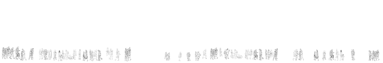
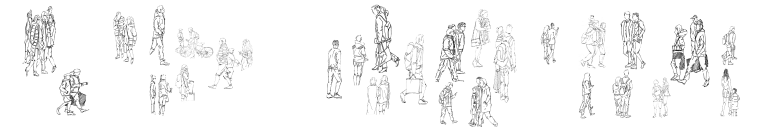
The last problem was the drawing of the background and people’s layers. Both were the core of my work, so from Monday I slept for two hours a day and I spent whole day to draw them.
10.17
– On 17 October, I only worked for drawing for background from morning to evening.

10.18
– On 18 October, I finished background drawing, scanned, drawn people, and separated them into individual PNG images.


10. 19
– On 19th October, was the day before the critique, so everything should have been finished. First, I did solder work that I couldn’t do at home. I started soldering at 11 o’clock, but it took more time than I thought. It was finished 3 o’clock. Cause, 5V (+) and GND (-) were soldered upside down, and I forgot to solder a resistor on the board.
When I returned home, after the soldering. I glued the box with glue gun, and placed Arduino and board that I soldered inside. The space was a bit narrower than I thought, but all went in.
After the box was created, I made the background and the people all on separate layers. I also modified the code a bit more, and it didn’t work as I expected, so I’ll have to ask the tutor after the critique.

10.20
Critic had been going on at 10.00 on Friday morning. Time was given for about 10 minutes per person. We started at 10:00 in the morning, but there were a lot of people in our year, it continued in the afternoon and until at 4.
I had a second announcement after lunch. After introducing my work, tutors mentioned they felt a more analog than digital in my work. My work was done on a digital basis, but the content inside was analog.
To briefly explain my work, it can be called ‘search of place’. This is similar to a ‘Hello World’ project that was my first interaction project. Aesthetically, it is a search for a place, theoretically it is detection of seeing, and it can be said that the design expresses the value for the future.
Also, when working, the interaction design needed to be melted non-visible things into the work, not just the visible things. I think I got it through a drawing. My drawing is not a mere imitation of reality, but it encompasses a personal vision, an idea, and my imagination. My drawing belongs to the field of emotion when it divides human perception into emotion and reason, which results in aesthetics. To summarize, art is “activity to communicate feelings”.
The theme of my work is a culture that lives and breathes in space. The place is the result of combination of space and culture. In other words, the place would be something made by human. A place occurs when it occupies a space and intentionally makes a relationship, but nothing happens in a vacuum without any interaction.
In addition, we live in a place that has a cultural meaning and influences each other. The place is a place where our lives are blended together. Internally, it has a profound impact on understanding our own identity and forming outwardly the view of the world. The city where these cultural traces of life are piled up is a cultural product created by the interaction of the local community for many years. It is a ‘landscape heritage’ produced by communicating with people. This is a work that says that it has a great historical and cultural meaning.
Based on this, I made a box and a controller through Arduino and processing, moved it, changed the landscape and the position of people in the work in real time, and placed it where I wanted. In this work, I recreated the work, meaning that people, cities, and surroundings all interact at the same time and form a relationship. I wanted to create a better work, but the time given for this project was up to this point, and if I had a better idea while doing other work in the middle, I would take notes and improve it gradually.
During this project, I had a lot of time to think about ideas, find materials, explore new programs such as Arduino and Premiere, and laser cutting and soldering. I’m looking forward to seeing what’s next project in terms of having more fun and new stuff.
Final documentation Link – https://youtu.be/8gzwmn7UE-g
Thank you for reading my blog 🙂
The Glasgow school of Art
Interaction Design Year 2
YongWon Choi
